I created an open-source syringe pump for my research in animal behavior. In my work, I often want to deliver a precise quantity of fluid, often as a reward for an animal. There are a few ways to do this, but I prefer syringe pumps as they are flexible and precise. Unfortunately, commercial syringe pumps can be rather expensive, and often lack the level of control that I need (for example delivering 1 mL of water contingent on a specific behavior). Due to these issues, I designed a syringe pump to meet my own needs. My pump delivers liquids through a 30 mL syringe. It can operate in the forward or reverse directions, but it is not intended for rapid, precise changes in direction. Instead, it is designed to empty the contents of a syringe, and then reset to an extended plunger position. My syringe pump includes two limit switches, at the front and the back, so that the plunger unit cannot be over extended. My design is provided “as is.” While I may make adjustments based on my needs or user feedback, my goal is not to market my design. Instead, I have created the pump for my personal use, and I ofter my design freely in case it may be of use to others. On this page, I provide instructions for my open-source design so that you can use my syringe pump for your own purposes. Below is a simple demonstration of the syringe pump.
I designed this syringe pump is so that I have something I can use for my own work that is easy to build, easy to use, and that has the type of control that my work requires. I also wanted a syringe pump design with minimal 3D-printed components, as these can be rather expensive if you do not have access to a 3D printer. There are a few other open-source designs, some of which appear to be good, such as this design at Hackaday, and some which I am rather skeptical of, such as this design published at PLOS ONE. I simply offer my design, as is, as an option. If you are interested in an open-source syringe pump, you are free to use my design, but you may find other open-source pumps, or even commercial pumps, to be a better fit for your needs.
Most of the parts of my syringe pump can be purchased online, only a few specialized parts are needed. Here is a link to my parts list. Some parts may be available for less at other vendors. You can download a SketchUp 3D model of my design here. The few custom parts my pump requires can be 3D printed from this model, or from this STL file. If you are not able to print locally, you can purchase the 3D printed parts from my shop at Shapeways. The total price of the parts is about $173 (not including shipping) if you order the 3D printed parts from Shapeways. If you are able to print the parts locally, the total price may be closer to $120. Around $25 of the price is for packs of various screws and nuts of which only a few are needed from each pack. You may be able to further reduce the total price if you can purchase the screws and nuts individually at some other vendor. I did not include parts for a microcontroller in my list, nor have I included prices for tools and wires. The parts list only covers the basic requirements for the syringe pump, stepper motor driver, and power supply. Each application will differ slightly in parts and price. I designed my syringe pump to work with this 30 mL syringe. However, you can also design different 3D printed parts, using the model I provided, to hold different, or even multiple, syringes. I designed the mechanical aspects of the pump around the largest syringe I wanted to use, so that I had the option of changing a few 3D printed parts to use a smaller syringe.
You can go to my syringe pump page on ServoCity's website to order all ServoCity parts with one click.
3D printing files - Optional
7/64" and 3/32" hex keys
Philips head screwdriver
Small slotted screwdriver ~3/32" wide
Soldering iron
Multimeter
An electric drill with various bits and sandpaper or a file may be useful
Software for the Propeller microcontroller - Optional
You will need to order the parts listed here. Keep the parts list handy as you are assembling the pump, the pictures on the vendors' websites can be useful. Three custom parts are also needed. They can be printed from Shapeways, or you can print them yourself from my Sketchup model or this STL file.

3D Model of the Syringe Pump. The front mount (green), mid mount (yellow), and plunger unit (blue) are the only custom parts that need to be 3d printed.
If you print the parts yourself on a fused filament fabrication (FFF) printer, you may need to separate the parts in the model into several smaller pieces, then print the pieces separately, and finally glue together each part. When I print from FFF printers, I use an arrangement as seen below. I print in ABS plastic and bind the pieces together using an acetone-ABS mixture. If you print from a service such as Shapeways, you can print each of the three complete parts without needing to glue the parts together. The tolerances for various 3D printers and materials vary, so you may need to sand the edges slightly or enlarge screw holes with a drill. For this tutorial, I printed the pieces in white ABS plastic, glued them together, then painted them black.
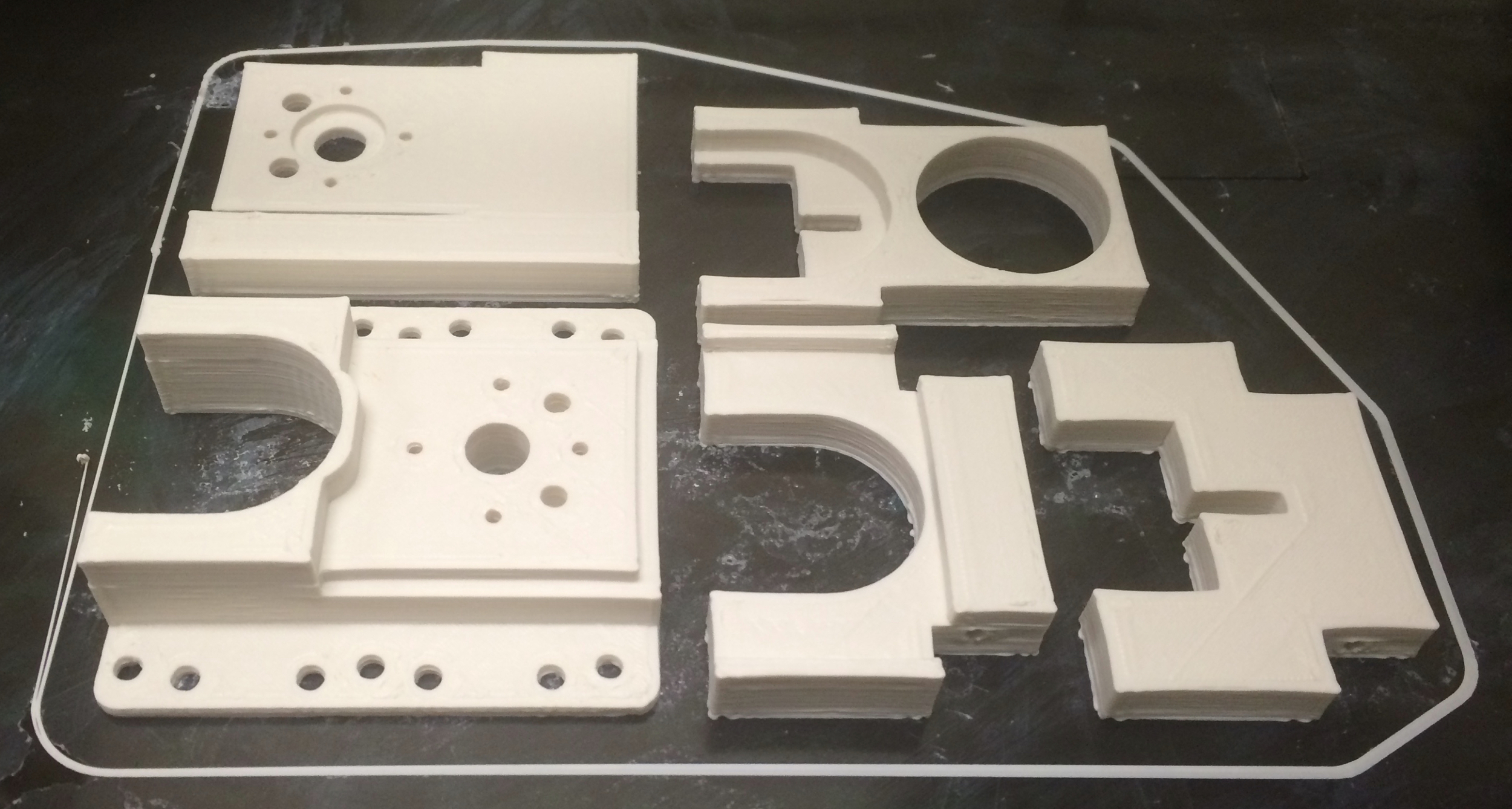
CUSTOM PARTS ON THE BED OF 3D PRINTER. THE MID MOUNT AND PLUNGER UNIT WERE BROKEN INTO SEPERATE PARTS FOR PRINTING AND REASSEMBLED LATER.

Assembled 3d Printed parts. From left to right: the front mount, mid mount, and plunger unit.
Once you have all the parts, you can begin assembling the syringe pump. First, attach the Actobotics stepper motor mount to the stepper motor using the four phillips head screws included with the stepper motor mount.
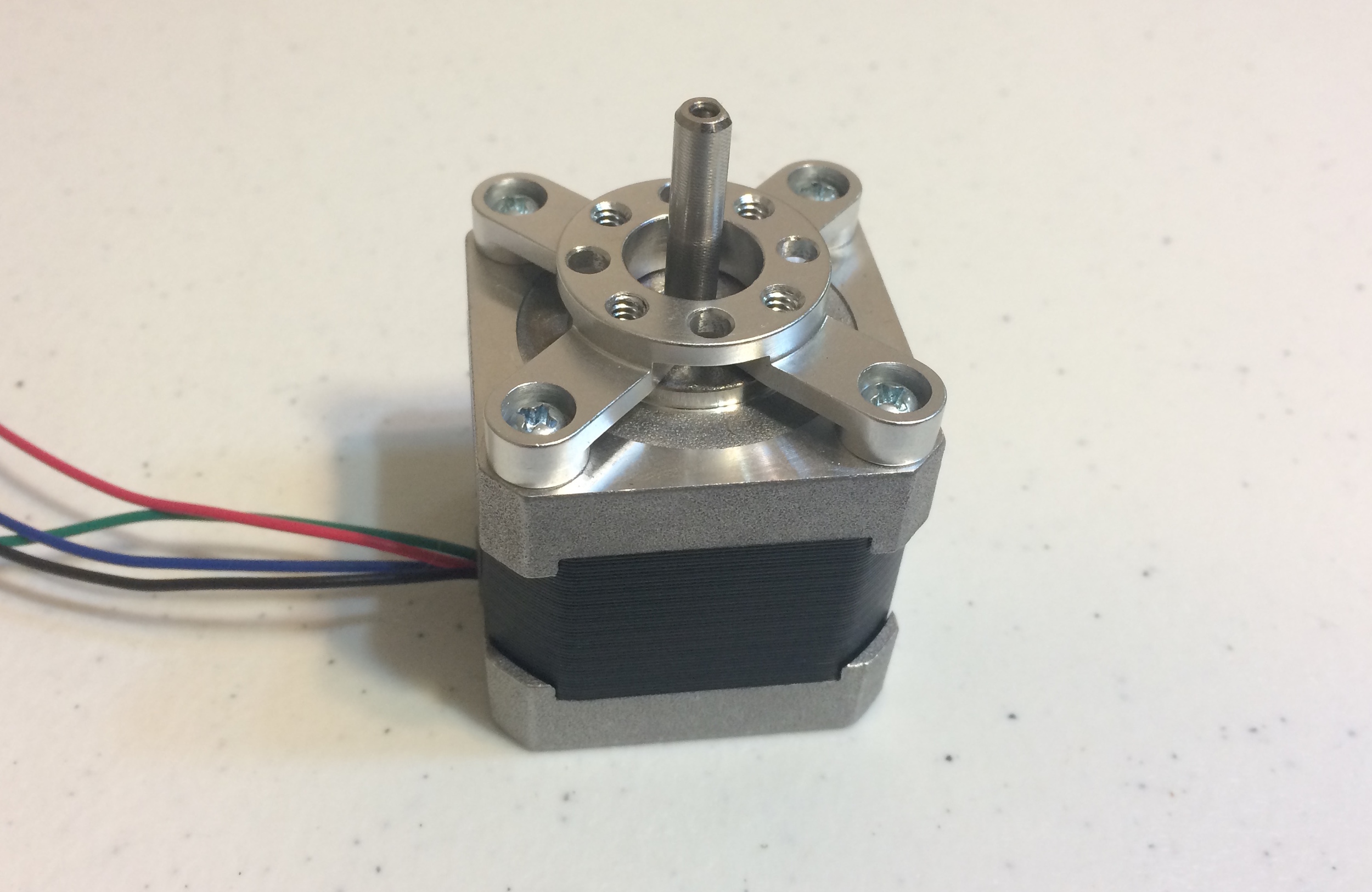
Stepper motor with actobotics stepper motor mount.
Next, attach the Actobotics side tapped pattern mount B (the round pattern mount) to the stepper motor mount using two 1/4" hex screws. Note the orientation of the pattern mount. The four mounting tabs should be facing away from the stepper motor. You will only need two screws to attach the pattern mount. Use the top two non-threaded holes on the pattern mount; the corresponding holes in the stepper motor mount are threaded. For this tutorial, I will consider the top of the stepper motor to be the side with the label and wires. We only use the top two mounting holes of the pattern mount to make the stepper motor easier to remove from the completed syringe pump (if ever required).
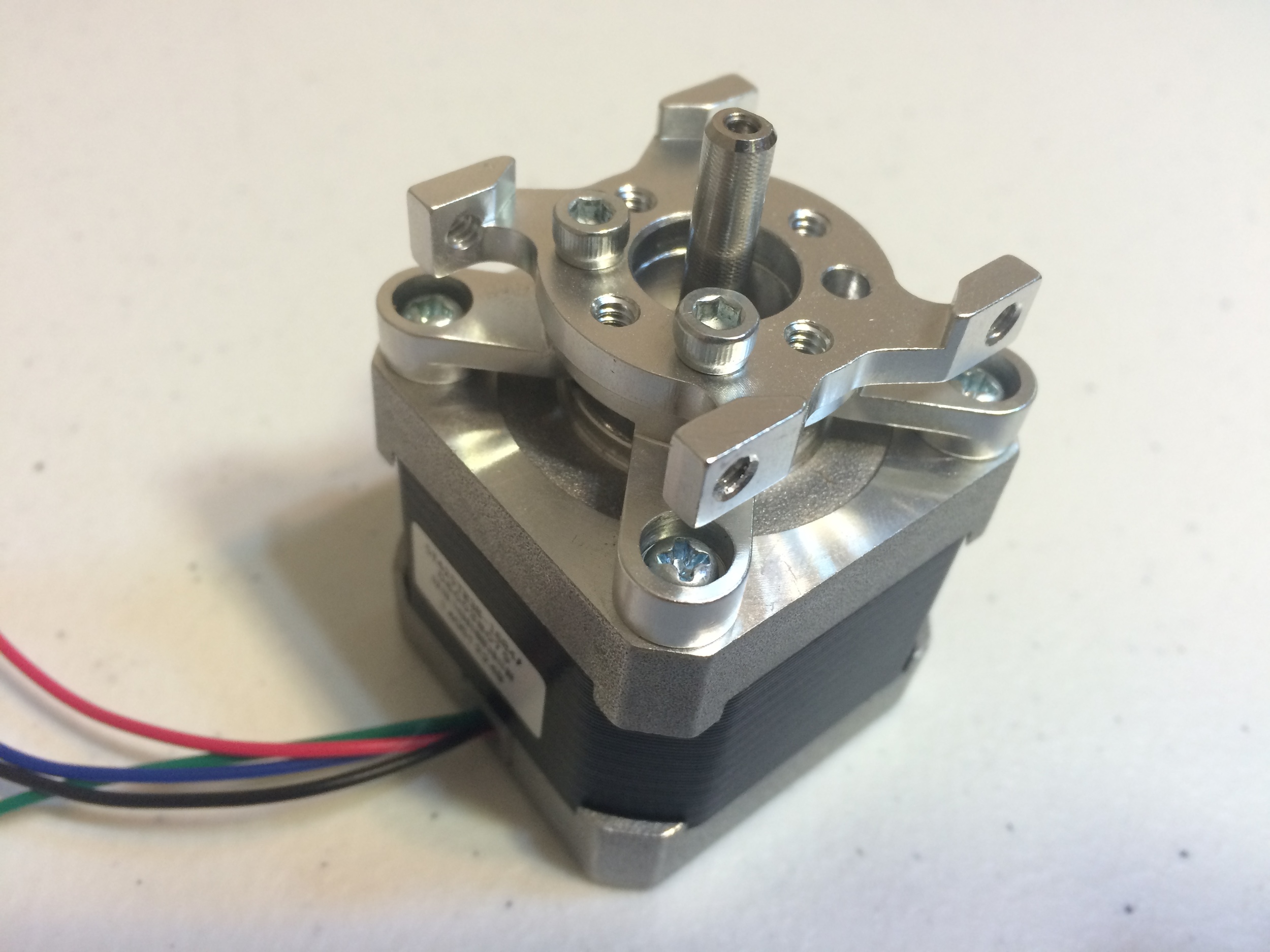
Stepper motor with WITH side tapped pattern MOUNT. NOTE THE ORIENTATION OF THE pattern MOUNT.
Next, we will add the 8 mm lead screw to the stepper motor assembly. Connect the larger end the shaft coupler to the lead screw, then connect the other end of the coupler to the stepper motor. One side of the stepper motor's drive shaft is flat; align the set screw to the flat portion of the drive shaft to lock the coupler in place. The lead screw, however, does not have a flat section, so the set screw will stick out a little. The connection should still be fairly snug. You have now assembled a "linear" stepper motor like those offered by Pololu, but at a fraction of the cost.

LINEAR STEPPER MOTOR WITH MOUNT.
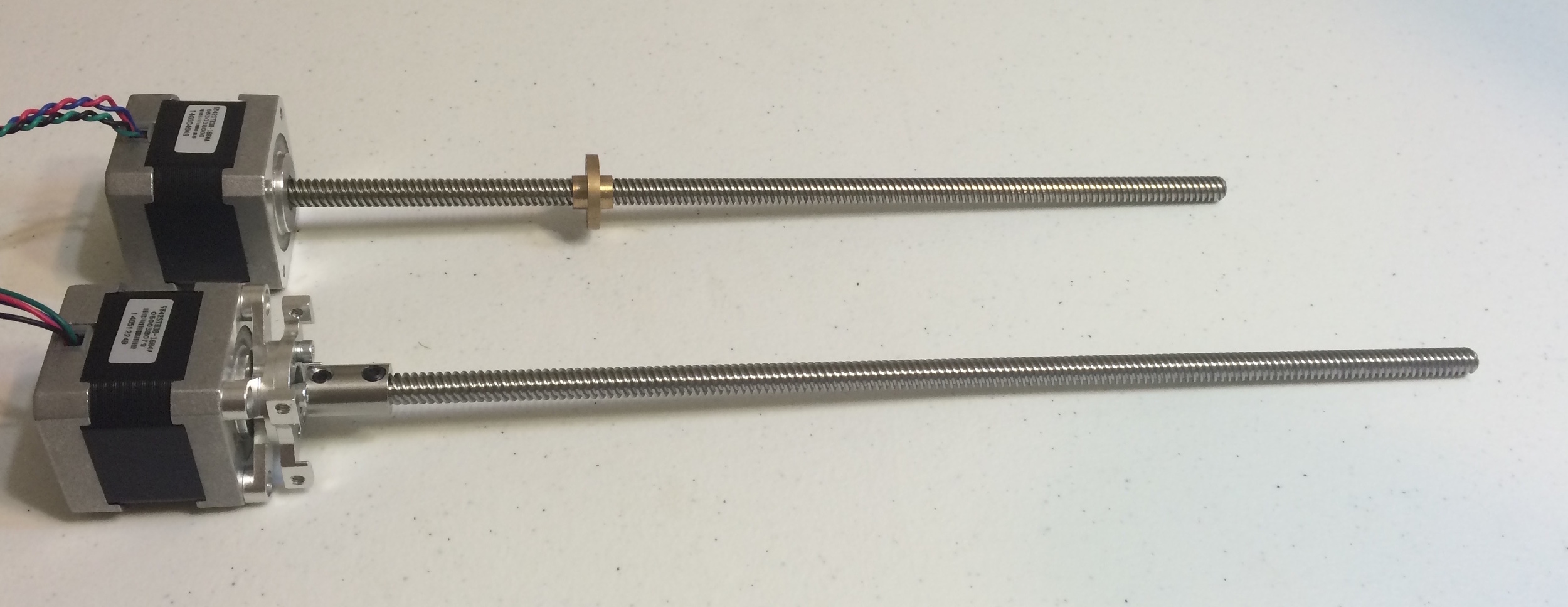
POLOLU LINEAR STEPPER MOTOR (TOP), AND CUSTOM LINEAR STEPPER MOTOR (BOTTOM).
Attach the stepper motor assembly to the 12" Actobotics channel using 1/4" hex screws. You will use the four side-facing mounting tabs of the side tapped pattern mount to secure the stepper motor assembly to the channel. Again, make sure the pattern mount is facing the correct direction. When you first place the pattern mount in the channel, you may encounter some difficulty positioning the lower two connection tabs. With a little force, or a few seconds of filing the pattern mount, the parts will fit. I suspect this may be an uncommon issue caused by slight inaccuracies in the aluminum channel, but the issue is fairly minor and it does not seem to reason for concern. Also note the orientation of the stepper motor assembly. Make sure the top of the stepper motor assembly is facing the open section of the channel. This will be the top of the syringe pump.

ACTOBOTICS CHANNEL WITH stepper motor assembly. NOTE THE ORIENTATION OF THE side tapped pattern MOUNT and stepper motor assembly.
Next, attach the lead screw nut to the plunger unit. Note that some holes in the lead screw nut are threaded, while others are non-threaded. Orient the plunger so that the top, bottom, left, and right holes are threaded, and the diagonal holes are non-threaded. Use 7/16" hex screws to attach the lead screw nut to the plunger. You may have to slightly enlarge the screw holes. The non-threaded holes in the plunger unit and lead screw nut should allow the 1/8" precision shafts to easily slide through the plunger without friction. If the holes are too tight, enlarge them now.
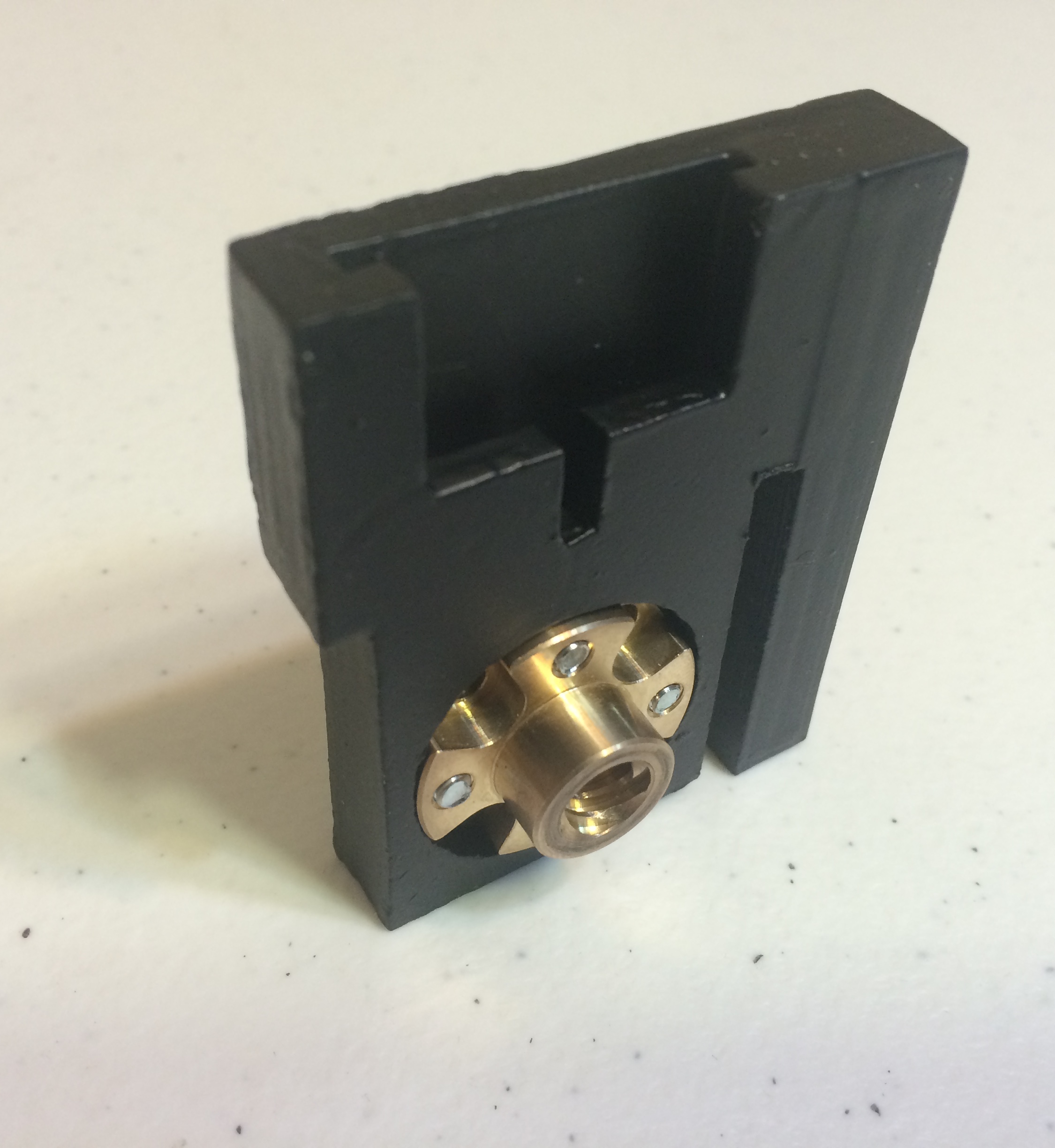
Front of PLUNGER UNIT WITH lead screw nut attached.

Back OF PLUNGER UNIT WITH LEAD SCREW NUT ATTACHED.
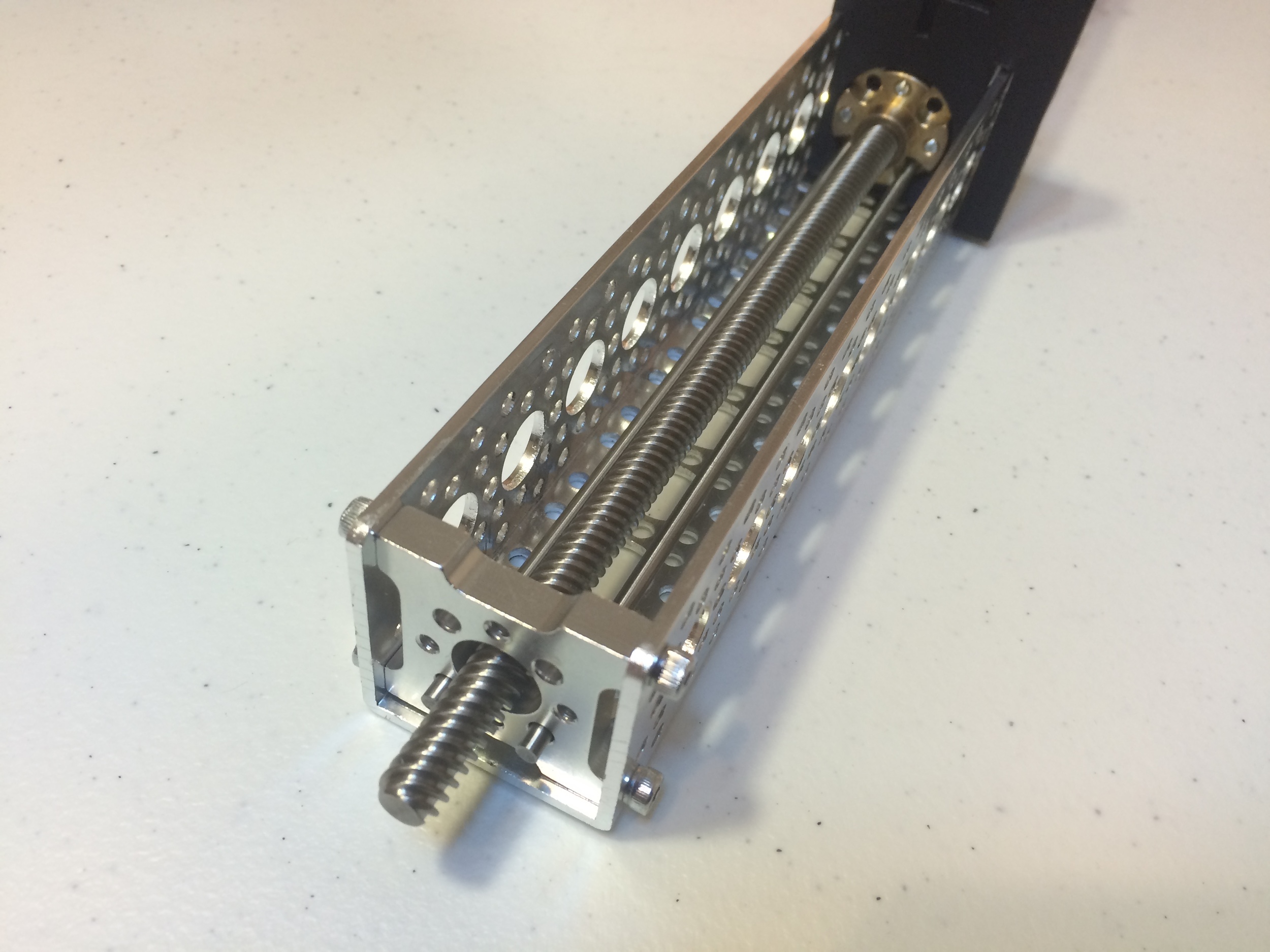
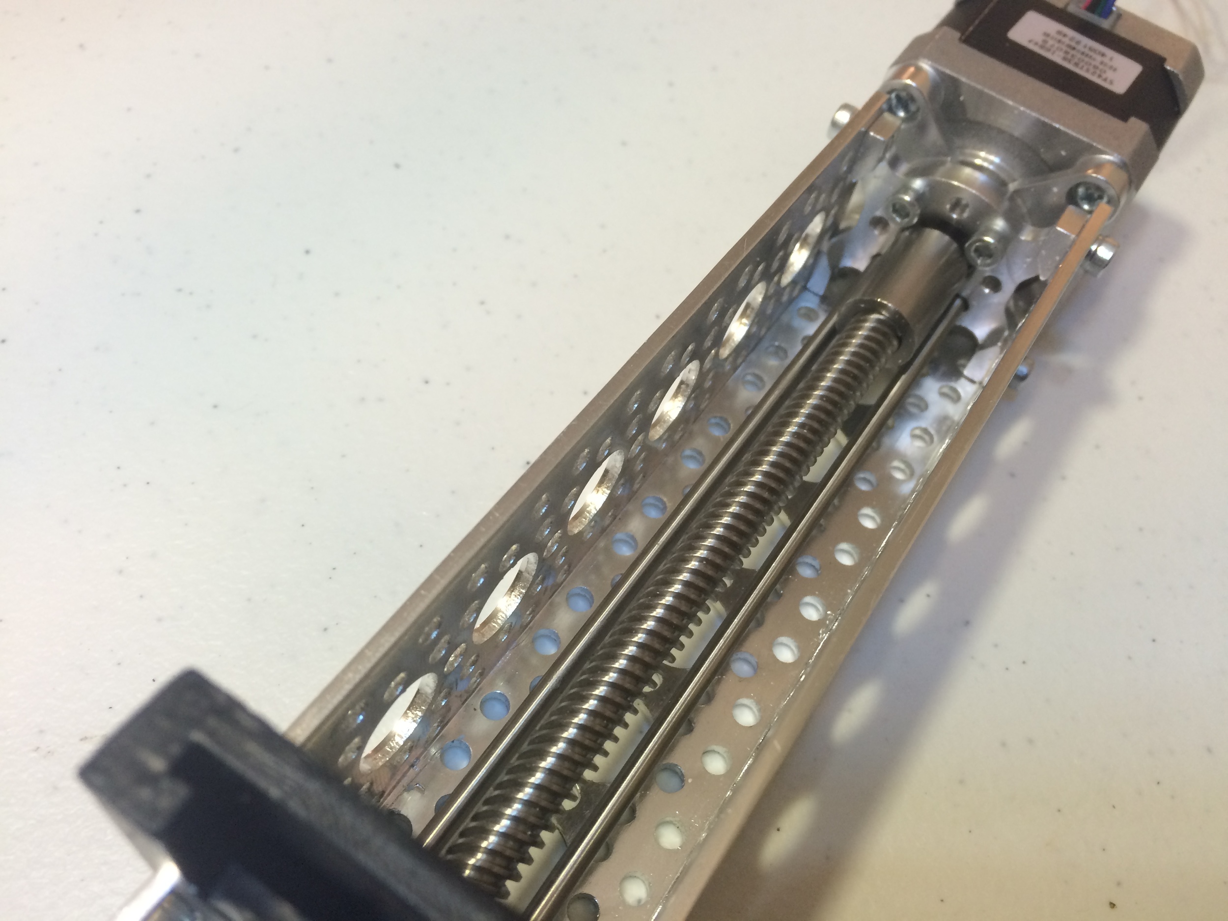
Thread the plunger unit onto the lead screw. Note the orientation of the plunger unit. You will want to continue to rotate the threaded rod by hand and move the plunger back until it is over halfway into the channel.

ACTOBOTICS CHANNEL WITH linear STEPPER MOTOR AND PLUNGER UNIT.
Attach the side tapped pattern mount D (the square pattern mount) to the front of the Actobotics channel. The pattern mount can be inserted facing either direction. Secure it to the channel with 1/4" hex screws.

ACTOBOTICS CHANNEL WITH LINEAR STEPPER MOTOR, PLUNGER UNIT and side tapped pattern mount D.
Insert the 1/8" precision shafts into the channel, through the front side tapped pattern mount D, through the plunger unit, and into side tapped pattern mount B attached to the stepper motor. The precision shafts should slide easily through the plunger unit. Needle nose pliers may be helpful when guiding the shafts through the other parts. The precision shafts will not be able to move much when the entire pump is assembled. They will be held in place by the stepper motor assembly and the 3D printed front mount.
ACTOBOTICS CHANNEL WITH LINEAR STEPPER MOTOR, PLUNGER UNIT, SIDE TAPPED PATTERN MOUNT D, and precision shafts. Front.
ACTOBOTICS CHANNEL WITH LINEAR STEPPER MOTOR, PLUNGER UNIT, SIDE TAPPED PATTERN MOUNT D, AND PRECISION SHAFTS. Back.
Next, attach the font mount to the side tapped pattern mount using 3/4" hex screws. The tips of the precision shafts should easily rest inside the holes in the front mount, and the tip of the threaded rod should pass through the front mount and turn without friction; enlarge these holes if needed. You may also enlarge the screw holes.
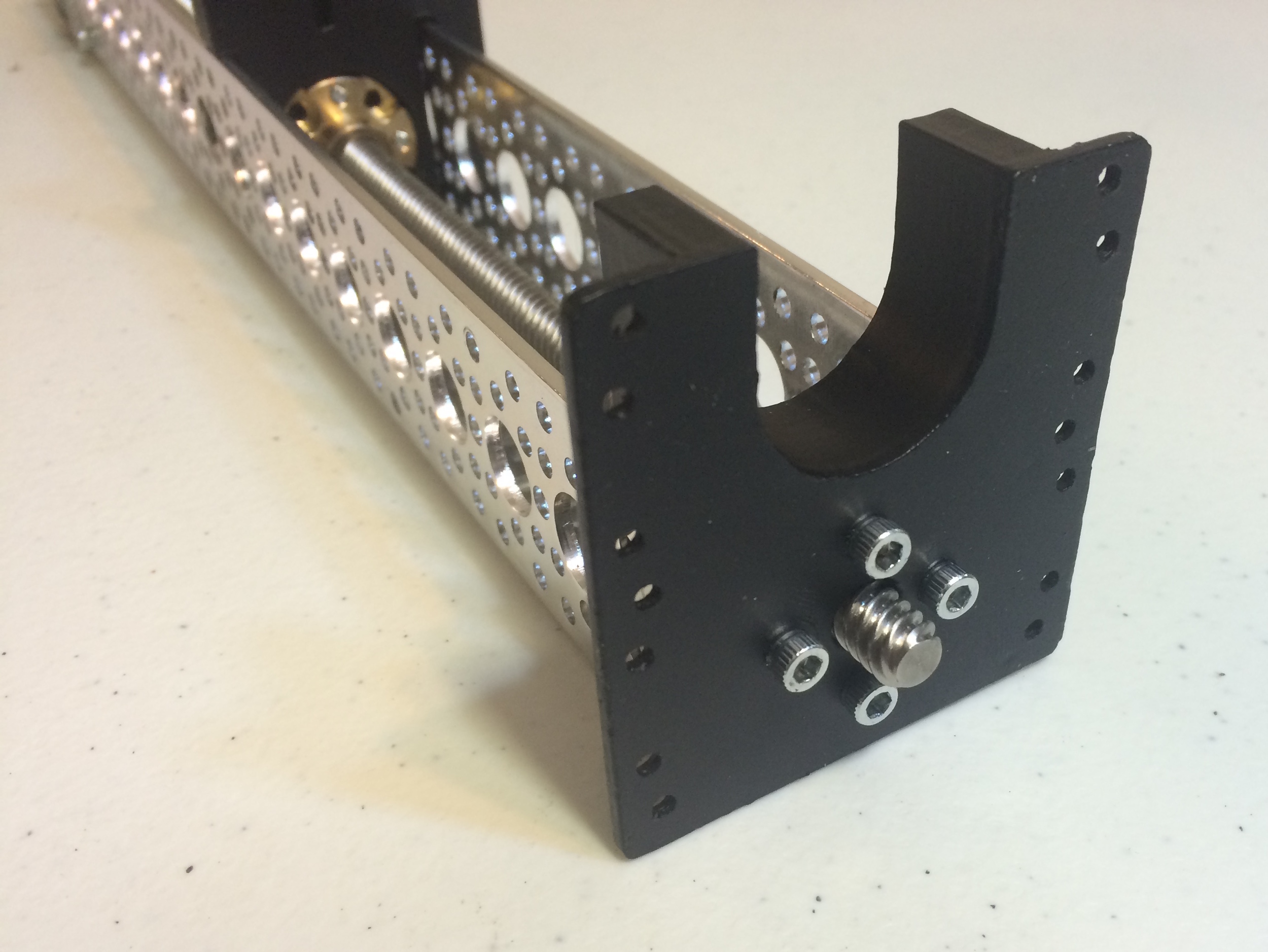
ACTOBOTICS CHANNEL WITH LINEAR STEPPER MOTOR, PLUNGER UNIT, SIDE TAPPED PATTERN MOUNT D, PRECISION SHAFTS, and front mount.
Add the mid mount to the channel using 5/16" set screws. Place the mid mount 12 upper-line mounting holes from the front, or 20 upper-line mounting holes from the back. Note the orientation of the mid mount. You may need to enlarge the screw holes slightly. Try not to enlarge these screw holes too much, as the plastic needs to have some threading to grip the screws. This is a good time to place a syringe in the pump to make sure all the parts are positioned correctly.
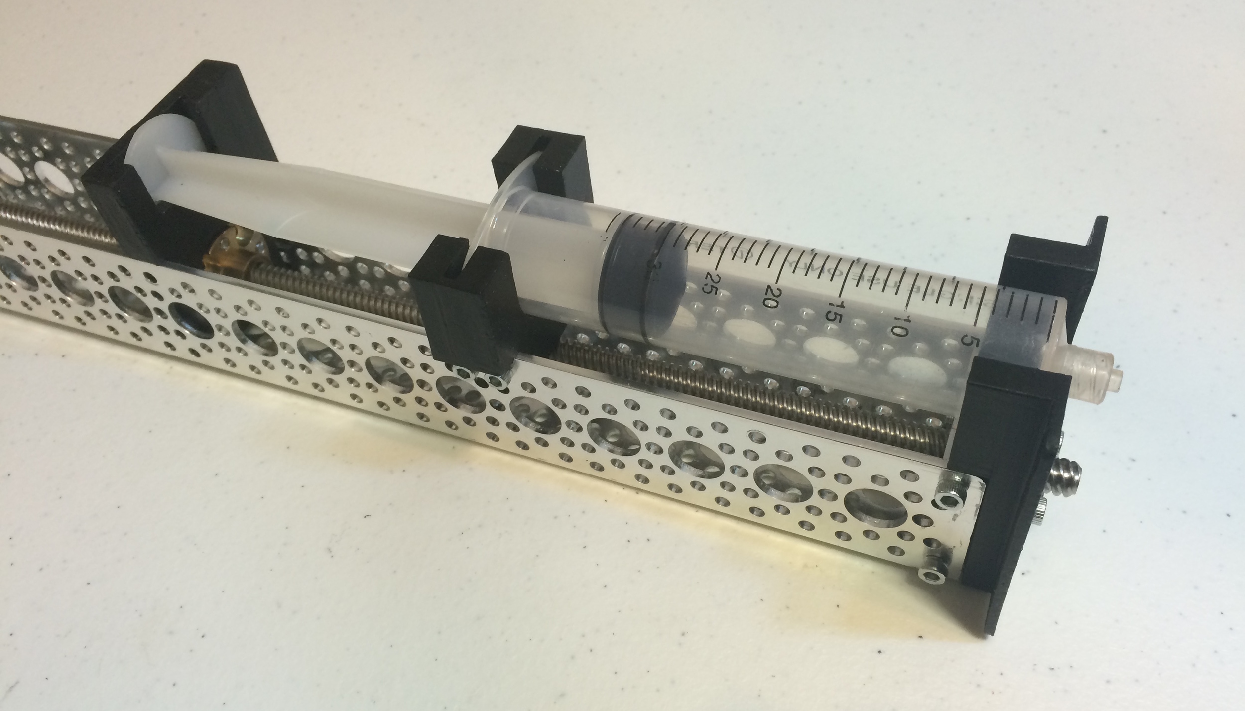
ACTOBOTICS CHANNEL WITH LINEAR STEPPER MOTOR, PLUNGER UNIT, SIDE TAPPED PATTERN MOUNT D, PRECISION SHAFTS, fRONT MOUNT, and mid mount
Connect the micro switches to the micro switch mounts. You may want to attach wires to the common (C) and normally closed (NC) terminals on the micro switches at this point. I prefer connecting wires after the switches are installed on the pump. When you are ready, attach the micro switch mounts to the left side of channel using 7/16" hex screws. One switch will face backwards at the 13th upper-line hole from the front of the channel, the other switch will face forwards at the 9th upper-line hole from the back of the channel. I use single screw plates to secure the bottom screws, and nylon nuts to secure the top screws of the micro switch mounts. I suggest using a pair of needle-nose pliers to hold the screw plates and nuts in place while you tighten the hex screws. Take note of the switch positions. You want the plunger unit to activate the switches before the plunger unit comes in contact with any other part of the pump, and before the syringe plunger is pushed too far forward or pulled too far backward. Check to make sure the switches appropriately restrict the plunger's movement. The micro switch mounts can slide back and forth a little on the hex screws. You may need to slide the micro switches forward or backward to get a good position relative to the plunger before tightening the screws.
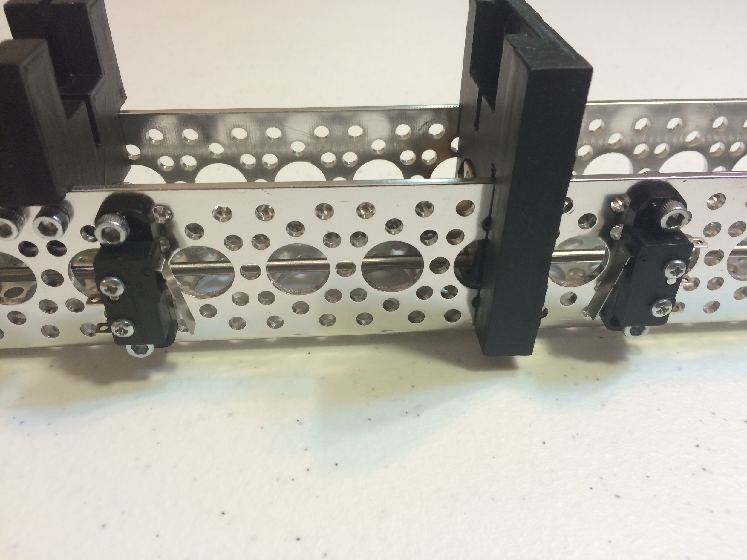
Installed micro switches. Outside view.
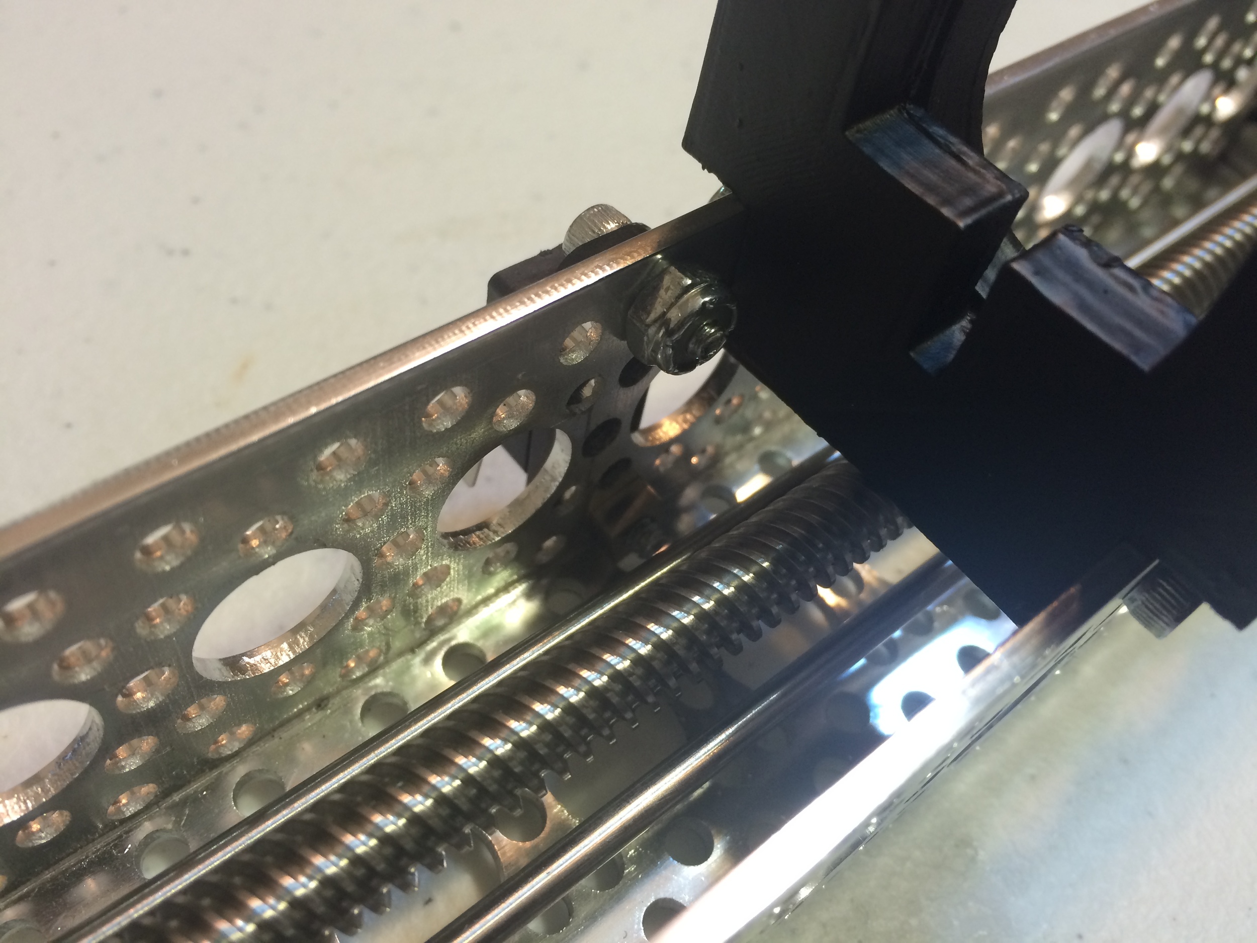
Inside view of one installed micro switch.
The mechanical components of the syringe pump are now assembled. You can now begin assembling the electronics.
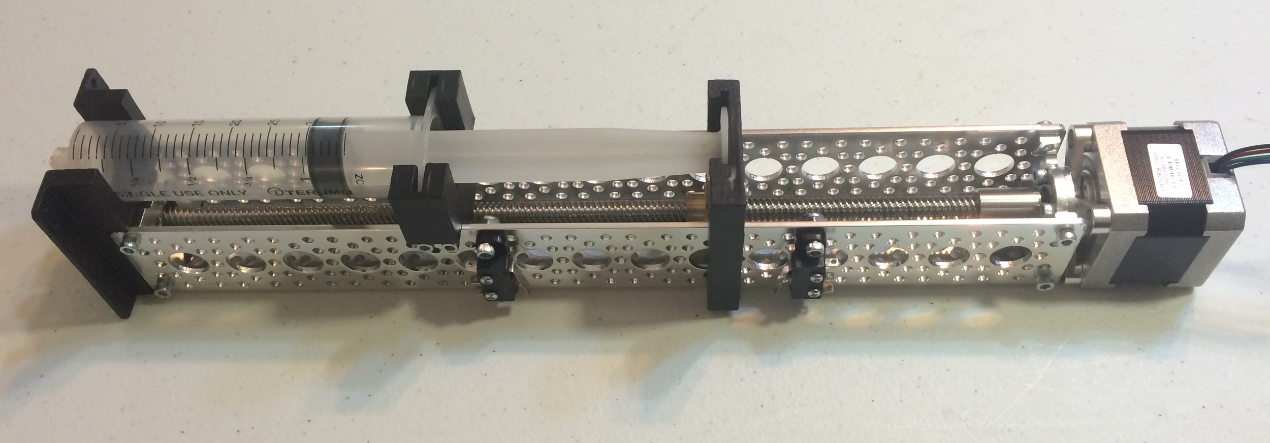
Completed syringe pump mechanical assembly.
The syringe pump can be controlled through a variety of electronic interfaces. I will leave you to decide a final solution for your application. However, to get you started, I will demonstrate how to control the syringe pump with a microcontroller and a driver circuit built on a solderless breadboard. You are free to use the microcontroller of your preference, but I will describe use with the Parallax Propeller microcontroller. I suggest reading this section COMPLETELY before assembling the electronics. If you make a single wrong connection, you could damage the pump and/or microcontroller. Also, make sure that the power supplies are NOT connected when you are preparing the circuits.
Stepper motors are more complicated than traditional motors, but they can be used for much more precise applications as they move in discrete steps. For some introductory material on stepper motors, see Adafruit's tutorial. There are many ways to control a stepper motor, but I prefer using Pololu's DRV8825 Stepper Motor Driver. This driver board costs a little more than designing your own control circuit, but the DRV8825 is efficient and flexible. I like this type of control method so that I spend less time designing electronics and more time actually using the pump. To use the DRV8825, I suggest soldering some pin headers to the board and following Pololu's minimal wiring diagram (See below). Connect the STEP and DIR pins of the DRV8825 to I/O pins on the Propeller. Connect the logic ground to the Propeller's ground. Connect the RESET and SLEEP pins to the Propeller's 3.3v logic supply. Once we have set up the driver, we will connect the SLEEP pin to an I/O pin on the Propeller to provide some additional control of the stepper motor and reduce unwanted noise. Next, connect the stepper motor power supply, but do not plug it in yet. I suggest this 24v 1.5amp power supply and detachable 3-prong power cord from Jameco. Connect the motor power supply to VMOT and GND, and add a 100 µF decoupling capacitor across the motor power supply, as close to the DRV8825 as possible. Please note that there are two GND connections on the DRV8825, one for the microcontroller, and one for the motor power supply. Do not confuse these.

Minimal wiring diagram.
Before connecting the stepper motor to the circuit, you need to set the current limiting potentiometer on the DRV8825. This driver is designed to work with a variety of stepper motors. You need to adjust the potentiometer so that the DRV8825 provides your motor as much current as possible without damaging it. Pololu has instructions on the DRV8825 product page as well as a tutorial video. The maximum current for this stepper motor, according to the product page, is 1.68 amps. However, the DRV8825 product page states that the board is rated for approximately 1.5 amps, unless a heatsink or other cooling method is used. We will use the equations Current Limit = VREF × 2 or VREF = Current Limit / 2 to limit the current supplied by the DRV8825 to 1.5 amps. VREF refers to a voltage reference measurement point on the DRV8825. To set the current limiting potentiometer, first check to make sure you have connected the DRV8825 correctly, make sure that the motor is not connected, and then connect the power supplies for the stepper motor and Propeller microcontroller (to simplify things, make sure the Propeller is running a blank program). Next, use a multimeter to measure the voltage from the GND pin to the VREF via, the small hole between the potentiometer and the integrated circuit on the DRV8825 board. Use a small flat head screwdriver to adjust the potentiometer. If we use the equation VREF = Current Limit / 2 we can find a goal VREF to obtain our desired current limit. To set the current limit to 1.5 amps, aim for a VREF of 1.32 volts. You may not be able to get exactly 1.32 volts, but try to get close to, or under the goal value.
Once the current limiting potentiometer is set, unplug both powers supplies and disconnect the SLEEP pin from the Propeller's 3.3v logic supply and instead connect the SLEEP pin to to an I/O pin on the Propeller. The Propeller will now be able to control the movement of the stepper motor, as well as put the DRV8825 to sleep when it is not being used. We left the SLEEP pin connected to 3.3v previously because we needed the DRV882 to be awake while we set the current limit.
Next, we can connect the stepper motor to the circuit. Make sure all power supplies are unplugged. The stepper motor can be easily damaged if it is connected or disconnected while the circuit is powered. Notice that the stepper motor has not two, but four wires. This is because the stepper motor has two coils inside it, each with a corresponding pair of wires. We need to find the pairs of wires for each coil. One easy way to do this is to connect an LED across a pair of wires, then manually rotate the stepper motor in either direction. The motor will act as a generator and cause the LED to illuminate if it is connected across two wires from the same coil. You should be able to rotate the stepper motor by manually turning the threaded rod at the front of the pump. For my motor, the green and black wires are part of one coil, and the blue and red wires are part of the second coil. Check your wiring, it may differ. Once you have identified the wires of each coil, connect the wires from one coil to the A1 and A2 pins, on the DRV8825 and the wires of the other coil to the B1 and B2 pins. This should ensure that the Propeller can control the motor, but the forward and backward directions may be reversed; we can check for this and fix it once we have a program running.
After you make the connections, your breadboard will look something like what I have below. (The pump in this section of the tutorial is an earlier version with white 3D printed parts and some minor differences in assembly, but the electronics remain the same.) Using this configuration, your stepper motor can be driven in whole steps. You will also be able to turn off the stepper motor driver by "sleeping" to save energy and to reduce heat and noise. The DRV8825 supports different configurations that may also be useful for you. For example, the M0, M1, and M2 pins can be used to make the motor move in smaller partial steps for more precise control. The current limiting potentiometer can also be adjusted in different ways for more precise current control.

Syringe pump, DRV8825 and Propeller Microcontroller. the limit MICRO switches are not yet connected. IN THIS IMAGE, THE SLEEP PIN ON THE DRV8825 IS STILL CONNECTED TO THE 3.3V SUPPLY.
In addition to the stepper motor circuit, you also need to connect the two limit micro switches, or limit switches. The limit switches will let the Propeller know when the plunger unit has reached the front and back limits of the syringe pump. Each micro switch has three labeled terminals, common (C), normally open (NO), and normally closed (NC). Connect both common terminals to the Propeller's 3.3v logic supply. Connect each normally open terminal to the Propeller's ground through a 10 kiloohm resistor and two I/O pins on the Propeller. The forward and back limit switches will be connected to separate I/O pins. For these instructions, as I had not yet decided on an permanent application for this syringe pump, I temporarily connected the limit switches with alligator cables.
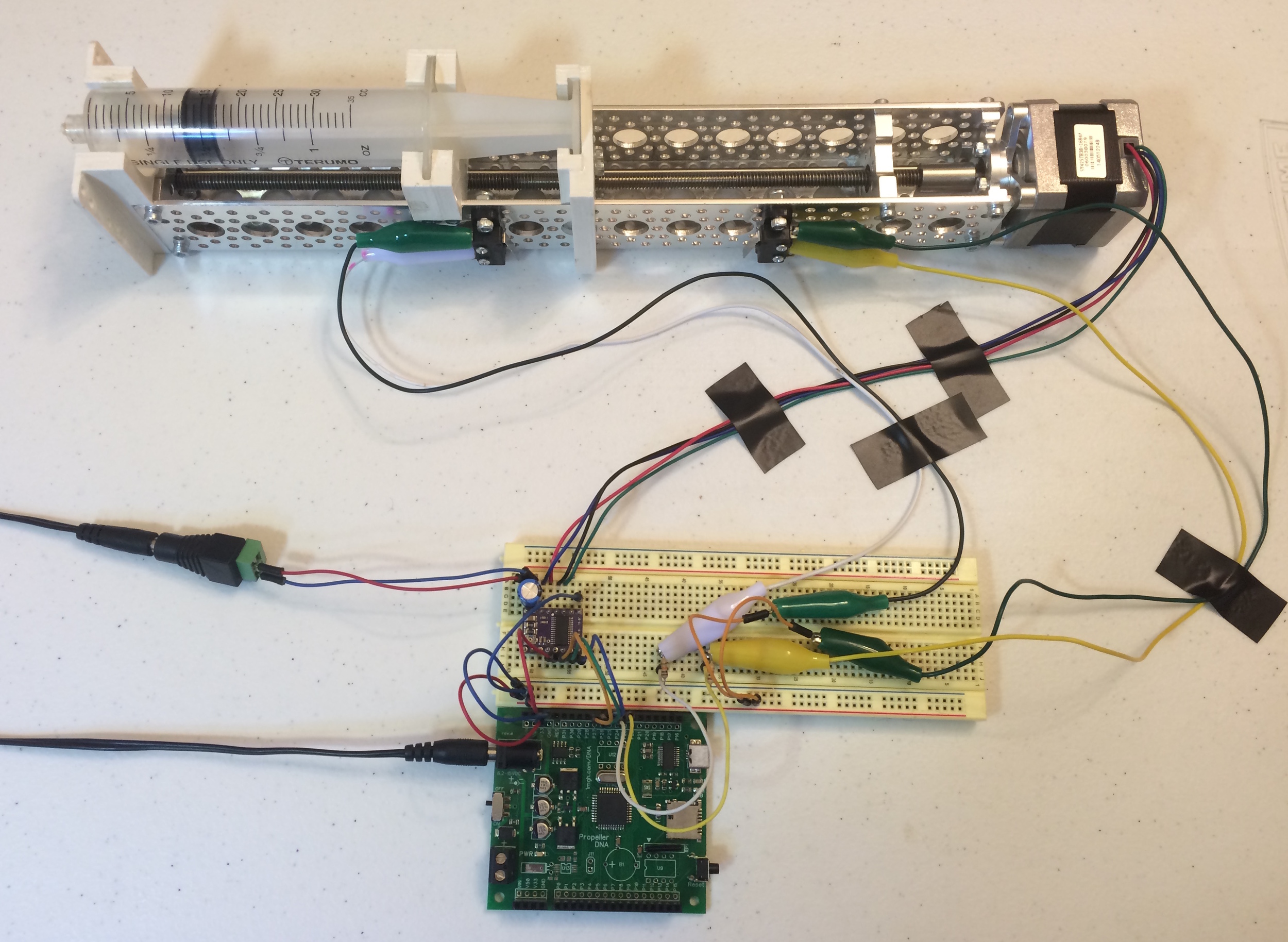
SYRINGE PUMP and completed circuit with DRV8825, PROPELLER MICROCONTROLLER, and limit micro switches. IN THIS IMAGE, THE SLEEP PIN ON THE DRV8825 IS NOW CONNECTED TO AN I/O PIN ON THE PROPELLER.
Above you can see the completed breadboard circuit. This circuit provides you with basic control of the stepper motor. For a permanent application, I recommend soldering together a more secure circuit. The stepper motor wires, and the alligator clips are likely to come lose with vibration or movement. Each application will likely also require additional components. Only three of the Propeller's 32 I/O pins are used, so you are free to connect a variety of other devices. The pump can also be easily installed in an apparatus through its many mounting holes. For outdoor use, I recommend adding a heatsink to the DRV8825. Sparkfun offers a small heatsink and thermal tape. Now that the circuit is set up, you can create a program, or use my programs, to test the pump.
Controlling a stepper motor based syringe pump through a dedicated driver like the DRV8825 is very easy. You can see details on the DRV8825 product page. For my work, I created an object in Spin for the Parallax Propeller microcontroller to control the syringe pump. You can download the syringe pump object here. For the Propeller, an object is a reusable library of code intended to be used by another program. My syringe pump object takes care of controlling the stepper motor in the background so that you are free to focus on creating the main program. To use my object, you will need to import it in the OBJ section of a program, then call the start method and provide pin numbers for the STEP, DIR, and SLEEP pins on the DRV8825, as well as pin numbers for the front and back limit switches. You also need to provide the address of a long-sized step variable. Once the start method is called, a new processor, called a cog, is launched to run the syringe pump control method in the background. The Propeller has eight independent cogs, so it is useful to dedicate a cog to a specific task. In the main cog, anytime the step variable is updated, the pump cog will move the pump forward or back that number of steps. If a limit switch is reached, the pump cog will not allow the pump to move further in that direction and will instead set the steps variable to zero. The demo program, pictured below, repeatedly moves the pump forward and backward 50,000 steps at a time, pausing for 500 milliseconds in between. Use this program to test your pump. You can download the demo program here. You will need to adjust the pin numbers in the CON section according to your connections.

Syringe Pump Demo Program.
There are a few things to test. First, note that when steps is set to a positive number, your pump should move forward and contract the syringe. If it does not, unplug your power supplies and reverse the connections of the stepper motor's wires. Remember that the four wires of the stepper motor are grouped into coil pairs. You already identified the pairs with the LED method, in the electronics assembly section. Keep your pairs together, but try reversing the order of the wires within the pairs. For my motor, I ended up connecting the wires to the DRV8825 as follows: A1-blue, A2-red, B1-black, B2-green. Once you have your motor wires correct, try adjusting the parameters in the program. What happens if you change the number of steps? What happens if you manually press one of the limit switches? Use and modify this demo program to get a feel for how to control the syringe pump. All you need to do is set the steps variable and let the pump cog do the work. When you are ready, you can incorporate the object into your own programs. If you want to understand how the syringe pump object works, look at the in-file commentary.
As I use the syringe pump, I will include some of the applications here. As of now, I have just completed documentation for the pump and will begin installing it in an operant conditioning apparatus. Look for updates later.
Design of research equipment is often an ongoing process. I have already made a few revisions to the syringe pump. So far, I have:
Selected a new lead screw and nut, resulting in much smoother movement, less wear on parts, and less noise.
Modified the plunger unit so that it grips the syringe plunger more tightly, allowing for more rapid changes in direction.
Modified the plunger unit so that it can never hit the screws or nuts of a limit switch before activating the switch.
Removed several parts to create a more inexpensive, efficient design.
Selected parts that are easier to install.
I am also considering additional revisions. Please let me know if you have suggested revisions. Here are a few revisions I am considering:
The positioning of various parts do not allow the syringe to empty completely. I am not sure if I consider this a flaw or a useful feature.
I am considering some attachments that might allow the syringe to be securely held in place even if the pump is upside down.